Showing posts with label structure. Show all posts

Thursday, February 17, 2022

NEW AGE OF CONSTRUCTION AND CONCRETE BLOCKS

 CONCRETE BLOCKS


Construction, as we know has come a long way thanks to the technological advancements giving us an upper edge to reinvent many construction materials. These upgrades have provided better strength and rigidity to the materials prolonging their age. 

One such advancement is Hollow Concrete Blocks. These have been inspired by the idea of providing heat and electrical insulation in buildings. As the name suggests, their core element is concrete and they are hollowed out from the middle. 

These blocks are available in the following sizes:

  • 39 X 19 X 30 cm ( standard size )
  • 39 X 19 X 20 cm
  • 39 X 19 X 10 cm 
Apart from imparting insulation, their smaller size and hollow middle allow more room space. Furthermore, the blocks are pre-cast, making their surface smooth and removing the need for plastering. 

In order to use these blocks in construction, the overall length and height of the wall are fixed accordingly so that a single block is used.

Hollow blocks are replacing the traditional use of bricks and stones, hence proving to be economic. 

Saturday, February 12, 2022

PARAPET WALL


 Word of the Day#2 

Parapet Wall:

A parapet wall is built when the outermost walls of a structure extend higher than the roof level around the edges, usually by a few feet.

The parapet wall can be seen in almost all structures like buildings, bridges, and roadways. These walls can be built using a variety of materials such as reinforced cement concrete, glass and steel, etc.


Thursday, January 27, 2022

PLASTERING

 PLASTERING

A thin layer of plastic mortar is put to the ceiling and walls to provide an even, smooth, uniform, and clean surface. This thin layer of covering is called as Plaster. Plastering is the technique of applying this layer to the surfaces. Plastering is done with plastic mortar, which is made by mixing some binding ingredient (like lime, cement, or mud) with fine aggregate and water in an appropriate proportion.


Some Commonly used Plaster:-

1. Lime Plaster:- Lime plaster refers to the use of lime as a binding material. Lime plaster is a form of plaster made of hydrated lime, sand, and water.


2. Cement Plaster:- It is a combination of portland cement, fine aggregates, and eater in appropriate proportions that is often applied to the interiors and exteriors of masonry to provide a smooth surface.


3. Mud Plaster:- It is composed of the proper proportions of clay and sand. This is the cheapest kind of plaster and is commonly used in case village and temporary kutcha buildings.


Tuesday, January 18, 2022

 Types of Wall in Building Construction

Wall:- Walls are necessary components of every structure. A wall is a structural component that divides a space into two spaces while simultaneously providing safety and shelter from the rain, sun, wind, theft, and other hazards.

  • Different Types of Walls are as follows:-

1) Load Bearing Wall:- As the name suggests, the complete structure is supported by walls rather than columns. In general, loads travel from the slab to the beams, then to the columns, and finally to the foundation. Load bearing walls support the entire structure's weight, including the self weight of structural parts. There are also different types of load bearing walls such as: retaining wall, precast concrete wall, masonry wall, stone wall, etc.

2) Non-Load Bearing Wall:- Non-load bearing walls solely hold their own weight and do not support any structural components like beams or slabs. The joists and rafters identify non-load bearing walls. These walls are only used as partitions or to divide rooms from the outside world. It is also referred as internal wall that does not support any other load but its own. There are also different types of load bearing walls such as: hollow concrete block, hollow brick, brick wall, etc.

3) Cavity Wall:- A wall made of two skins of masonry, the outermost part of which can be brickwork or blockwork and the innermost part of which is usually blockwork. A cavity wall provides superior thermal insulation than any other solid wall.

4) Partition Wall:- A partition wall is a non-load bearing internal wall that divides a large space into small spaces. It can be solid, made of brick or stone. It is a framed structure. The partition wall is both a sound barrier and a fire barrier.

5) Panel Wall:- It is a non-bearing wall that is supported by columns or pillars. It is used for aesthetics of the buildings both inside and outside. It remains totally supported at each storey but subjected to lateral loads.


Saturday, January 15, 2022

Post-Tensioning

 Post-Tensioning

Post-tensioning is a technique used to produce prestressed concrete, masonry, and other structural components. In this process, steel tendons are tensioned after the concrete has been placed. The tendons are stretched between sturdy bulkheads that can bear external stresses before being surrounded by concrete. 


When is the structural element is heavy, the post-tensioning method is recommended. Construction that would normally be unfeasible due to site limitations or architectural requirements has become possible due to this technique. It is a technique that needs specific expertise and well-trained personnel. This procedure could be used on any structure, whether residential, commercial, or office buildings. It is widely used in bridges, floor slabs, silos, and other concrete structures.

Monday, January 3, 2022

TYPES OF JOINTS IN A STRUCTURE

TYPES  OF JOINTS IN A STRUCTURE

In any type of structure, consideration is given towards structural damages. These damages can be either sudden or over the course of time. Either way, it is to be ensured that the damage is minimized by any means. For all these dimensional changes, the structure is broken down into different components which when joined together form a joint.

Different types of joints are provided in a structure:

  • Expansion Joint: This type of joint is provided, keeping in mind of the thermal expansion property of concrete. With an increase in temperature, concrete can expand  which in turn can form cracks. To avoid the formation of cracks, expansion joint is provided which allows for free movement of concrete.


  • Contraction Joint: This type of joint is inverse in comparison to the expansion joint. Aim is the same as expansion joint ( to prevent the formation of cracks ) the only difference being that this is provided for the case where the temperature drops.


  • Sliding Joint: As the name suggests, this joint is provided to allow free movement between two components of a structure. This joint is usually provided under the foundation keeping in mind the horizontal forces ( shear stress ) applied by the subsoil on concrete. 


  • Isolation Joint: This joint serves the purpose of isolating one structural component from the other. This joint is usually made from asphalt-impregnated fiberboard, cork, rubber or neoprene. 


Saturday, January 1, 2022

Tests on Concrete

 TESTS ON CONCRETE

There are certain types of tests performed on concrete in order to ensure it's workability, tensile strength, etc. Different types of tests are used to determine different results.

1. Rebound Hammer Test:

Rebound Hammer Test is used to determine the compressive strength of concrete. Apparatus consists of a Rebound Hammer or Schmidt Hammer. Hammer consists of a spring controlled mass contained in a tubular house which slides on a plunger. When the rebounded hammer plunger is pressed against the surface of concrete, the spring controlled mass is released and made to hit the concrete surface and rebound. The amount of rebound is a measure of hardness of concrete surface. This rebound is measured on a graduated scale and the measured value is called the Rebound Number. Concrete with high strength will reveal a higher Rebound number and vice versa.

2. Penetration Resistance Test: 

This test is used to determine the uniformity and assess the in-situ strength of concrete. Test is conducted using Windsor Probe test machine. A steel probe is fired on the surface of concrete sample with a sudden explosion. The amount of penetration is inversely proportional to the strength of concrete. Strength of aggregates and nature of formed surfaces of concrete can influence the result of this test. 

3. Ultrasonic Pulse Velocity Test: 

Idea behind Ultrasonic Pulse Velocity test is to measure the time taken by an ultrasonic pulse to pass through a concrete sample. This test is performed in-situ to assess the quality of concrete ( homogeneity, check presence of cracks and overall imperfections ). The concrete sample is induced with a series of waves. A transducer is placed on the other side to detect the ultrasonic waves. The speed of wave is affected by the shape, size and geometry of concrete. Concrete with homogeneity and uniformity will allow the waves to pass through quickly and vice versa. 

4. Core Sampling of concrete:

Concrete core or core sampling makes use of a rotary cutting tool with diamond bits. This is used to obtain a cylindrical specimen . The cores are documented on site. ( visually observed and photographed ) Next it is soaked in water, made even over it's surface and tested for compression in a moist condition as per BS: 1881: Part 4: 1970. 

5. Water Absorption Test: 

This test is used to determine the durability of concrete. In this 3 cubes of 150mm concrete sample are taken and and placed in a curing tank for 28 days or after 24 hours the concrete is removed from the mold and sent to a third-party laboratory for curing. The testing is done in accordance with BS: 1881-122.

Saturday, December 25, 2021

Methods of Surveying

METHODS OF SURVEYING

Surveying means finding the position of any given point on, above or below the earth's surface with respect to a point and plotting it on a map using suitable scale. Surveying measurements are taken only in the horizontal plane. Surveying involves leveling which refers to the elevation of a point with respect to benchmark point. 

PRINCIPLES OF SURVEYING

There are 2 principles of surveying:

  • Location of a point by measurement from 2 points of reference: This principle states that the relative position of a point should be located by measurement from at least 2 reference points whose positions have already been fixed. 
  • Working from whole to part: This principle suggests that surveying should be carried out from whole to part meaning for an area to be surveyed, reference points should be setup which cover the whole area. From there other small details should be located. With this method the chances of error are reduced by a great amount. 
METHODS OF SURVEYING

There are 2 primary methods of surveying:
  • Plane surveying: In this method the spherical shape of earth is neglected. Instead earth is assumed to be a plane surface and all the triangulations carried out are considered plane triangles. This is typically carried out for an area for 250 km sq.
  • Geodetic surveying: This is a more precise method of surveying, reason being the earth is taken in it's original spherical shape and all respective calculations are carried out accordingly. This methods makes triangulation much more precise compared to plane surveying and is hence carried out for areas exceeding 250 km sq.
The secondary methods of surveying are as follows:

  •  Chain surveying: Chain surveying is the oldest method in the books of civil engineering. The area to be surveyed is divided into smaller areas. The measurement of each divided area is carried out separately. The method is called chain surveying because the instrument used for taking measurements is a 20m chain. The chain has a brass ring at every meter and a tally at every 5 meters. The measurements are carried out accordingly and the individual areas are summed up in the end. Condition for this type of surveying is that the area to be surveyed should be small.
  • Compass surveying: Compass surveying employs the use of triangulation and internal angles for carrying out the calculations. In this we use a prismatic compass for measuring the bearing of a line. With respect to that bearing we find the angles of the respective triangle and lengths are measured with chain. 
  • Plane Table surveying: Idea behind plane table is that the entire area is divided into stations. These stations are separately worked on by drawing rays on paper as a reference line and carrying out measurements from that line. The results are plotted on paper with a suitable scale. Condition for this method is that every other station should be parallel to the previous one. 
  • Theodolite surveying: In this we used theodolite which is an instrument used to measure horizontal angles, vertical angles, deflection angle and difference in elevation. Theodolite is accurate between 10" - 20". With theodolite we find the desired elevations and angles and then carry out the necessary calculations. 
  • Tacheometric surveying: In this we make use of an instrument called tacheometer which works similar to theodolite, difference being the tacheometer has a different lens as compared to theodolite. Working is carried out the same way with tacheometer finding the horizontal and vertical distances by taking angular observations. 

Thursday, December 23, 2021

Types of Loads acting on a structure

 TYPES OF LOADS ACTING ON A STRUCTURE 

Any type of structure is subjected to different types of loads. These loads can be vertical, horizontal or even longitudinal loads. 

According to IS: 875 - 1987 The different types of loads are:

1. Dead load: Dead loads compose of those loads which are stationary. They are also called permanent loads because they are applied on the structure throughout it's lifetime. Mostly these comprise of structure's self -  weight, fittings, partitions, etc. 

2. Live load: Live loads are also referred as imposing or sudden loads meaning they can change with respect to time. These loads comprise of furniture, equipment, people.

3. Wind load: As the name suggests, this load is imposed due to the wind movement and the direction and intensity with which it moves. Factors taken during calculation of wind loads are wind speed, direction of wind and height of building.

4. Earthquake load: This load is taken in consideration for the case of an earthquake striking the structure. During an earthquake there is lateral ground movement, hence the load applied on the structure is horizontal according to the force exerted by the ground. Vertical component is also taken into consideration but that is mostly due to structure's own weight.

5. Snow load: This load is not typically taken into consideration while designing a building. This is exclusive for structures which receive snowfall. Calculation are done with respect to height of building, shape and size of the roof. 

Tuesday, December 21, 2021

Types of Soil Testing for Construction

TYPES OF SOIL TESTING FOR CONSTRUCTION  

Soil tests are carried out to ensure optimum conditions for the soil hence making sure the working conditions are as per requirements for a smooth construction. Technically it is the first step in any construction activity as the entire load of a structure is transferred to the soil and if the soil conditions are not optimum, chances of structure failure are quite high. 

Different types of soil tests are carried out accordingly.

1. Core cutter method:

This method is used to find the in-situ dry density of soil. 

( condition: it is only used in case of fine grained soil )

This method involves,

  • a cylindrical core cutter ( 130mm in length and 100mm in diameter )
  • a steel dolly ( 25mm high and 100mm in diameter )
  • steel rammer ( 9kg mass and 900mm length )
  • weighing balance
PROCEDURE:
  • Determine the volume of core cutter by measuring the internal dimensions.
  • Calculate the weight of core cutter without dolly.
  • Drive the cutter into the soil by placing dolly over the cutter.
  • Remove the cutter containing soil.
  • Remove the dolly and trim off the excess soil.
  • Calculate the weight of cutter filled with soil.
  • Take the representative sample and repeat the test three/four times and calculate the average density.
2. Sand Replacement Method:

This method is also used for dry density testing of soil.

This method involves,

  • sand pouring cylinder
  • calibrating container
  • tray with circular hole
  • chisel
PROCEDURE:
  • Fill the cylinder with uniformly graded sand up to a height of 10mm below the top.
  • sand is made to pass through 600 micron sieve and retained on 300mm sieve.
  • This weight is recorded as M1.
  • Place the sand pouring cylinder over a plane surface and open the shutter to allow the sand to fill the cone.
  • This weight is recorded as M2.
  • Collect the sand on the plane surface and transfer it back to the pouring cylinder.
  • Place the sand pouring cylinder over the cylindrical can and allow the sand to fall into the cylindrical can till it is full. 
  • Once the sand is filled, close the shutter.
  • Measure the weight of pouring cylinder again and this is noted as M3.
  • Calculate the unit weight of sand.
3. Calculation of Liquid Limit using Casagrande's apparatus:

Liquid limit refers to the moisture content at which the soil sample can flow and close a groove of standard width.

This method involves,
  • Casagrande's apparatus
  • Grooving tool
  • Wash bottle 
  • Palette knives
PROCEDURE:
  • Pass approximately 120g of soil sample through a 425 micron IS sieve and mix it with distilled water.
  • Take into consideration that the paste should be consistent.
  • Place the sample in the cup and with the help of a spatula, spread it across the entire cup to be uniform.
  • With the help of a grooving tool, make a sharp groove along the diameter from the center.
  • Drop the cup from a height of 10mm by cranking it at a rate of 2 revolutions/sec until the two halves of the soil cake come in contact with the bottom of the groove at a distance of 12mm.
  • Make a note of the number of drops required to close the gap of 12mm.
  • Repeat the procedure about 4 times and record the observations.
  • Plot a graph of the recordings and the moisture content corresponding to 25 drops is taken as the liquid limit of the soil.
4. Shrinkage limit test on soil:

When the water content is sufficient enough to fill all the pores of the soil and the soil is saturated, that is known as shrinkage limit. It is defined as the lowest water content at which the soil is completely saturated.

This method involves,

  • Shrinkage dish
  • Evaporating dish
  • Glass cup
  • Spatula
  • 425 micron IS sieve
  • Balance
  • Mercury
PROCEDURE:
  • Pass 100g of soil sample through 425 micron IS sieve.
  • Mix 30g of soil sample with distilled water in an evaporating dish till the voids are completely filled.
  • Weigh an empty shrinkage dish. This weight is taken as W1.
  • Grease the inside of the dish to prevent adhesion and fill the shrinkage dish in 3 equal layers.
  • Weigh the shrinkage dish with wet soil. This weight is taken as W2.
  • First the sample is dried at room temperature for approx. 24 hours and then shifted to oven at 105 - 110 degree celsius. 
  • Note the weight of oven dried shrinkage dish. This weight is taken as W3.
  • Remove the soil cake from the shrinkage dish. 
  • Remove the excess mercury from the paste by placing sponge on top of the soil cake. Gently transfer this over a dry container and make a note of the weight as Ws.
  • Carry out the necessary calculations.
5. Proctor's Compaction Test:

Compaction refers to the mechanical effort applied over a soil in order to rid it of the void space between particles. 

This method involves,

  • Rammer of mass 2.6kg
  • Compaction mould of capacity 1000ml
  • IS sieve ( 4.75mm )
  • Oven 
  • Weighing balance 
  • Mixing pan
  • Spatula
  • Mixing tools
PROCEDURE:
  • Pass 20kg soil through 4.75mm IS sieve.
  • Calculate the percentage retaining on sieve and the percentage passing the sieve.
  • 100mm of mould is used for this procedure. Mix both the soil percentages.
  • Grease the mould and base plate and weigh them to the nearest accuracy.
  • Add water to the soil and keep it in an air tight container for about 18 - 20 hours for maturing and mix it thoroughly.
  • Divide the sample into 6 parts.
  • Take 3kg of soil and place it in the mould in 3 equal layers.
  • Take one third of the sample and compact it by giving 25 blows of the rammer. Distribute the blows uniformly over the soil layer. Repeat it for the second and third layer.
  • Trim the excess soil and remove the mould. Weigh the sample.
  • Determine the water content for the top, middle and bottom layer and carry out the necessary calculations.


Friday, December 17, 2021

 TYPES OF PILE FOUNDATION

  • SHEET PILES: Equipped with a vertical interlocking system, sheet piles are long structural sections that create a continuous wall which is used to retain soil or water. The dependency of a sheet pile's ability to perform is on the geometry and the type of soil it is driven into. The pile transfers pressure from the high side of the wall to the soil in front of the wall.


  • LOAD BEARING PILES: Load bearing pile are used to transmit the load of a structure through a soil layer which is too weak to support the structure. Pile acts as a column to transfer the load through the weak layer to a stronger layer. This type of pile is designed similar to a reinforced concrete column except the buckling is not considered in the design. 


  • FRICTION PILES: Also called floating piles, friction piles receive their bearing capacity through shear stresses along the sides of the pile. They are best used in places where the hard layers of the soil are too deep to reach. Friction piles transfer the load from the topsoil to the bottom with the help of adhesion between pile surface and soil. 


  • TIMBER PILES: Like the name suggests, this type of pile is made from timber obtained from teak, sal, deodar, etc. They can be square or circular in shape. 


Thursday, December 16, 2021

Pile foundation

 PILE FOUNDATION

In case where the shallow foundation has adequate capacity to support the load of the superstructure then shallow foundation is provided but if the soil is poor, the depth of foundation has to be increased in order to safely transmit the load. Because of this increased depth the foundation is known as deep foundation and pile foundation is one such type of deep foundation along with piers and wells.


TYPES OF PILE FOUNDATION

Pile foundations can be classified into different types based on certain criteria. 

1. BASED ON FUNCTION OR USE

A. Sheet piles

B. Load bearing piles 

C. End bearing piles

D. Friction piles 

E. Soil compactor piles


2. BASED ON MATERIAL AND CONSTRUCTION METHOD 

A. Timber piles

B. Concrete piles

C. Steel piles 

D. Composite piles

These can be further classified into the following:

  • Timber piles: Untreated and Treated with Preservative 
  • Concrete piles: Pre cast piles and Cast in-place piles 
  • Steel piles: I - section piles and Hollow piles
But the best way of classifying pile foundation is on the basis of effect of installment of pile on the soil. Based on this pile foundation is divided into 2 types:
  • Displacement piles
  • Non - displacement piles
USES OF PILE FOUNDATION
  • Piles provide load transfer in cases of poor/weak soil.
  • In foundations for retaining walls, bridge abutments piles are used to resist horizontal loads.
  • Loose sand deposits which get densified by the vibration set up on driving are compacted using piles.
  • Piles are useful in resisting uplift loads.

Monday, December 6, 2021

Foundation selection based on soil types

FOUNDATION SELECTION BASED ON SOIL TYPES

Foundations are selected based on the type of soil reason being not every foundation can be supported on every soil type because of their varying textures and properties.

Foundations are selected based on the following types of soils: - 

1. Rocks

2. Uniform, firm and stiff clay 

3. Soft clay

4. Peat


1. Rocks: - Rocks, hard sound chalk, sand, and gravel with limited clay content and dense silty sand all fall under this group.

The foundations recommended for this soil type are:

1. Raft foundation

2. Pad foundation

3. Strip foundation

2. Uniform, firm and stiff clay: - This type is divided into 3 cases:

  •  If the foundation is adjacent to the vegetation or where the presence of vegetation is unimportant.

The foundations recommended for this case are: -

1. Raft foundation

2. Strip foundation

3. Pad foundation

  •  Where there are trees, hedges and bushes near the foundation or where there is a proposal to plant these plants near the structure in the future.

The foundations recommended for this case are: -

1. Concrete piles supporting reinforced concrete ground beams and precast concrete floor.

2. Raft foundation.

3. Specially designed trench fills in certain clay soil based on the foundation location relative to trees. 

4. Concrete piles carrying in situ concrete slab.

  • Where trees are felled just prior to the start of foundation construction

The foundations recommended for this case are: -

1. Strip foundation

2. Raft foundation

3. Reinforced concrete pile in previously tree root zone

3. Soft Clay: - soft clay, soft silty clay, soft sandy clay and soft silty sand all fall within this group. 

The foundations recommended for this case are: -

1. Pile to firmer strata below

2. Wide strip footing

3. Raft foundation

4. For smaller projects use pier and beam foundation to firm strata.

4. Peat: - The foundations recommended for this case are as follows:

1. Raft foundation for the case where firm strata is not available at reasonable depth but there is hard surface crust within 3-4mm thick of suitable bearing capacity.

2. Concrete piles extended to the firm soil layer below.

3. For small projects, pad and beam foundation are taken to the firm strata below.


Monday, November 29, 2021

Foundation and it's importance

 FOUNDATION AND ITS IMPORTANCE


    Foundation is the most important member of any structure since the entire structure rests on the foundation and it is responsible for transferring the entire load of the structure down into the soil. 

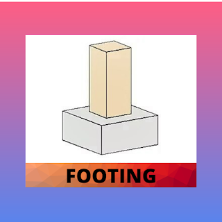
The foundation makes up the substructure of any building meaning it is a member below the soil whereas the member above the soil is called Superstructure. Furthermore, the foundation is supported by another member called Footing. 

The footing serves as an important asset to the foundation as it helps direct the load evenly in the soil. Raw soil in itself is not strong enough to take the load from the foundation reason being its uneven nature. Therefore it is not capable of providing enough opposing force for the incoming load ( according to newton's third law of motion ) hence putting the structure at great risk of sinking into the soil. Footing transfers the load over a large area so that the pressure does not exceed its allowable bearing capacity.


TYPES OF WALLS

  TYPES OF WALLS Walls as we all know have been the defining points of any and all kinds of structures. Walls represent the extent of any st...